Free tool
How to Read Blueprints
A set of blueprints looks like a wall of lines until you know the order to read it. Start with the index and title block, check the scale, then work from the floor plan out to elevations, sections and details. The two small tools below decode sheet numbers such as A-101 and check that dimension strings add up.
Blueprint sheet number decoder
Discipline: A
Architectural
Sheet type: 1
Plans
Sequence
Sheet 01 in this group
Architectural (plans, elevations, sections, details). Plans (horizontal views, such as floor plans and roof plans).
Dimension string checker
Copy the small dimensions along one wall and the overall dimension printed above them. They should agree. Type feet and inches like 12-6 or 12-6 1/2. A bare number is feet.
Segments add up to
32'-0"
Overall shown
32'-0"
The segments add up to the overall dimension.
How to read blueprints, step by step
Every sheet in a set follows the same layout, so once you can read one you can read them all. The sample sheet below has the five parts you meet first. The numbers in the drawing match the steps in the list.
- Open the cover sheet and sheet index. It lists every drawing in the set, so you know whether the plans include structural, plumbing and electrical sheets as well as the architectural ones.
- Read the title block (callouts 1, 2, 3 and 6). It sits in the bottom right corner and gives the project name, the sheet title, the scale and the sheet number. Look at the revision box too, so you are not building from an old issue.
- Check the scale (callout 3) and the north arrow. Do not assume one scale for the whole set: a floor plan may be 1/4" = 1'-0" and a wall detail 1-1/2" = 1'-0".
- Read the floor plan first (callout 4). It is a view from above, with the building cut roughly 4 feet above the floor. Walk through it room by room, from the front door.
- Follow the dimension strings (callout 5). The outer string gives the overall size, the inner strings give the rooms and openings. Add the small numbers and check they match the overall one.
- Use the elevations to see each outside wall, the sections to see floor-to-ceiling heights and how the roof, walls and floors are built, and the details for anything drawn at a larger scale.
- Finish with the schedules and general notes. Door, window and finish schedules say exactly what each tag on the plan means. Written notes and dimensions override what you measure with a ruler.
Symbols and line types are covered on our blueprint symbols page, so keep that open while you read: it explains what the arcs, dashed lines and small circles on the plan stand for.
Types of drawings in a set of plans
| Sheet | What it shows | Read it for |
|---|---|---|
| Site plan | The lot from above: boundaries, building outline, driveway, utilities | Setbacks, where the house sits, access |
| Floor plans | Each level cut about 4 ft above the floor | Room sizes, walls, doors, windows, stairs |
| Elevations | Each outside wall: front, rear and sides | Heights, roof shape, materials, window positions |
| Sections | The building sliced vertically | Ceiling heights, floor and roof build-up, stairs |
| Details | Close-ups at a larger scale | How parts join: eaves, sills, footings |
| Schedules | Tables of doors, windows and finishes | Sizes, types and finishes of each tagged item |
| Foundation and framing plans | Footings, slab, joists, beams, rafters | What carries the load and at what spacing |
| Electrical, plumbing and mechanical plans | Outlets, fixtures, pipes, ducts | Where services run and what they connect to |
What the sheet number A-101 means
Most US plan sets follow the National CAD Standard for sheet numbers. A-101 has three parts: a letter for the discipline (A for architectural), a digit for the type of drawing (1 for plans), and two digits for the order within that group (01 is the first). Some firms write the same sheet as A1.01. The decoder above reads both styles.
| Letter | Discipline |
|---|---|
| G | General: cover sheet, index, notes |
| C | Civil: grading, drainage, site utilities |
| L | Landscape |
| S | Structural: foundation and framing |
| A | Architectural: plans, elevations, sections, details |
| I | Interiors |
| P | Plumbing |
| M | Mechanical: heating, cooling, ventilation |
| E | Electrical |
| Digit | Sheet type | Example |
|---|---|---|
| 0 | General | A-001 legend and notes |
| 1 | Plans | A-101 first floor plan |
| 2 | Elevations | A-201 exterior elevations |
| 3 | Sections | A-301 building sections |
| 4 | Large-scale views | A-401 enlarged kitchen plan |
| 5 | Details | A-501 wall details |
| 6 | Schedules and diagrams | A-601 door and window schedules |
How to read scale and dimensions on a blueprint
The scale says how much smaller the drawing is than the real building. At 1/4" = 1'-0", a quarter inch on the paper is one foot in the building. To read a length, measure it in inches and divide by 0.25: a wall that measures 3-1/8 inches long is 12'-6" in real life. Metric sheets use ratios such as 1:50 or 1:100, where 1 cm on paper is 50 cm or 100 cm in the building.
Use a scale ruler, or convert the numbers with our architectural scale converter. If the sheet has a graphic scale bar, hold your ruler against it first. A PDF printed with "fit to page" is no longer at the stated scale, and the bar shrinks with it.
| Scale | Ratio | Common use |
|---|---|---|
| 1/8" = 1'-0" | 1:96 | Large floor plans, site plans for small lots |
| 1/4" = 1'-0" | 1:48 | House floor plans and elevations |
| 3/4" = 1'-0" | 1:16 | Wall sections and larger details |
| 1-1/2" = 1'-0" | 1:8 | Small construction details |
| 1:50 and 1:100 | 1:50, 1:100 | Metric floor plans and site plans |
Dimension strings are easier to trust than a ruler. Most are measured to the outer edge of the studs or the masonry, and the plan notes which. When a written dimension and a scaled measurement disagree, the written dimension wins, and a larger-scale detail wins over a smaller-scale plan.
Common mistakes when reading blueprints
- Measuring a printout that was scaled to fit the page. Check the graphic scale bar first.
- Reading a sheet marked NTS (not to scale). Use the written dimensions only.
- Skipping the general notes and schedules. A tag such as W3 on a plan means nothing until you look it up in the window schedule.
- Mixing up sheets from different issues. Match the revision letter or date in the title block on every sheet you use.
- Reading only the architectural sheets. Beams, ducts and plumbing runs on other sheets can change what fits in a wall or ceiling.
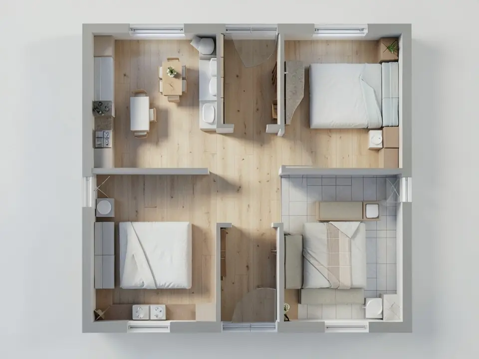
Turn a 2D floor plan into a 3D render
Upload a floor plan or blueprint and our AI renders it as a furnished 3D view, so clients and family can see the rooms instead of reading the symbols.
Try floor plan to 3D renderSign in with Google or email to render. New accounts get 1 free render (watermarked).
Frequently asked questions
How do I read blueprints for beginners?
Start with the sheet index and the title block, check the scale, then read the floor plan room by room. Move on to the elevations, sections and details, and finish with the schedules and general notes.
In what order should I read a set of blueprints?
Cover sheet and index, then the site plan, floor plans, elevations, sections, details and schedules. Read the structural, plumbing, mechanical and electrical sheets after the architectural ones.
What does A-101 mean on a blueprint?
A is the architectural discipline, the first digit 1 means a plan sheet, and 01 is the first sheet in that group. A-101 is usually the first floor plan.
How do you read the scale on a blueprint?
Find the scale in the title block or under the drawing. At 1/4" = 1'-0", every quarter inch you measure on paper is one foot in the building. Divide the measured inches by 0.25 to get feet.
What are the main types of drawings in a blueprint set?
Site plan, floor plans, elevations, sections, details and schedules, plus structural, electrical, plumbing and mechanical sheets on larger projects.
Are blueprints really blue?
Not any more. The original blueprint process made white lines on blue paper. Plans today are plotted in black on white or shared as PDFs, but the name stuck.
More free tools for architects and designers
- Blueprint symbols chart
- Architectural scale converter
- Architectural paper sizes
- Floor plan to 3D render
- House plans
- Tile calculator
- Roof pitch calculator
- Architectural scale converter
- Cost to build a house calculator
- King size bed dimensions
- Standard door sizes
- Standard window sizes
- Bathroom vanity height
- Two car garage dimensions
- 1200 sq ft house plans
- Free house plans
Sources: Sheet numbering follows the US National CAD Standard (sheet identifiers: discipline letter, sheet type digit, sequence). Scales and drawing practice follow common US architectural drafting conventions.